LOGO!Power 24 V DC
Overview
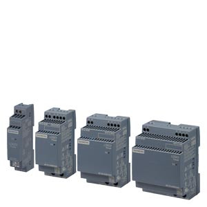
Thanks to its stepped profile design, the LOGO!Power product line is ideally suited for installation in small distribution boards. The stabilized power supplies with wide-range input are available with an output voltage of 24 V in four performance classes. The 24 V versions are ideal for supplying LOGO! PLCs with the corresponding voltage input.
To further increase the 24 V availability, the LOGO!Power power supply units can be combined with DC UPS, redundancy and selectivity modules.
Product highlights
- 1-phase, 24 V DC/ 0.6 A, 1.3 A, 2.5 A and 4.0 A
- Input voltage 100 … 240 V AC (85 … 264 V), 110 … 300 V DC
- Narrow unit with width of 18 mm, 36 mm, 54 mm or 72 mm and overall depth of 53 mm in LOGO! design
- Up to 90% efficiency
- Integrated current monitor: Actual output current measurement directly at the power supply unit (for devices at least 36 mm wide)
- cULus, cURus, NEC class 2, ABS, BV, DNV GL, LRS certifications
Specifications
| Article number | 6EP3330-6SB00-0AY0 | 6EP3331-6SB00-0AY0 | 6EP3332-6SB00-0AY0 | 6EP3333-6SB00-0AY0 | |
| Product | LOGO!Power | LOGO!Power | LOGO!Power | LOGO!Power | |
| Power supply, type | 24 V/0.6 A | 24 V/1.3 A | 24 V/2.5 A | 24 V/4 A | |
| Input | |||||
| type of the power supply network | 1-phase AC or DC | 1-phase AC or DC | 1-phase AC or DC | 1-phase AC or DC | |
| supply voltage at AC | |||||
| ● minimum rated value | 100 V | 100 V | 100 V | 100 V | |
| ● maximum rated value | 240 V | 240 V | 240 V | 240 V | |
| ● initial value | 85 V | 85 V | 85 V | 85 V | |
| ● full-scale value | 264 V | 264 V | 264 V | 264 V | |
| input voltage | |||||
| ● at DC | 110 … 300 V | 110 … 300 V | 110 … 300 V | 110 … 300 V | |
| design of input wide range input | Yes | Yes | Yes | Yes | |
| overvoltage overload capability | 300 V AC for 1 s | 300 V AC for 1 s | 300 V AC for 1 s | 300 V AC for 1 s | |
| operating condition of the mains buffering | at Vin = 187 V | at Vin = 187 V | at Vin = 187 V | at Vin = 187 V | |
| buffering time for rated value of the output current in the event of power failure minimum | 40 ms | 40 ms | 40 ms | 40 ms | |
| operating condition of the mains buffering line frequency | at Vin = 187 V | at Vin = 187 V | at Vin = 187 V | at Vin = 187 V | |
| ● 1 rated value | 50 Hz | 50 Hz | 50 Hz | 50 Hz | |
| ● 2 rated value | 60 Hz | 60 Hz | 60 Hz | 60 Hz | |
| line frequency | 47 … 63 Hz | 47 … 63 Hz | 47 … 63 Hz | 47 … 63 Hz | |
| input current | |||||
| ● at rated input voltage 120 V | 0.3 A | 0.7 A | 1.22 A | 1.95 A | |
| ● at rated input voltage 230 V | 0.2 A | 0.35 A | 0.66 A | 0.97 A | |
| current limitation of inrush current at 25 °C maximum | 20 A | 25 A | 52 A | 31 A | |
| I2t value maximum | 0.8 A²·s | 0.8 A²·s | 3 A²·s | 2.5 A²·s | |
| fuse protection type | internal | internal | internal | internal | |
| ● in the feeder | Recommended miniature circuit breaker: from 6 A characteristic B or from 2 A characteristic C | Recommended miniature circuit breaker: from 6 A characteristic B or from 2 A characteristic C | Recommended miniature circuit breaker: from 10 A characteristic B or from 6 A characteristic C | Recommended miniature circuit breaker: from 10 A characteristic B or from 6 A characteristic C | |
| Output | |||||
| voltage curve at output | Controlled, isolated DC voltage | Controlled, isolated DC voltage | Controlled, isolated DC voltage | Controlled, isolated DC voltage | |
| output voltage at DC rated value | 24 V | 24 V | 24 V | 24 V | |
| output voltage | |||||
| ● at output 1 at DC rated value | 24 V | 24 V | 24 V | 24 V | |
| relative overall tolerance of the voltage | 3 % | 3 % | 3 % | 3 % | |
| relative control precision of the output voltage | |||||
| ● on slow fluctuation of input voltage | 0.1 % | 0.1 % | 0.1 % | 0.1 % | |
| ● on slow fluctuation of ohm loading | 0.1 % | 0.1 % | 0.1 % | 0.1 % | |
| residual ripple | |||||
| ● maximum | 200 mV | 200 mV | 200 mV | 200 mV | |
| ● typical | 30 mV | 30 mV | 30 mV | 30 mV | |
| voltage peak | |||||
| ● maximum | 300 mV | 300 mV | 300 mV | 300 mV | |
| ● typical | 50 mV | 50 mV | 50 mV | 50 mV | |
| adjustable output voltage | 22.2 … 26.4 V | 22.2 … 26.4 V | 22.2 … 26.4 V | ||
| product function output voltage adjustable | No | Yes | Yes | Yes | |
| type of output voltage setting | via potentiometer | via potentiometer | via potentiometer | ||
| display version for normal operation | Green LED for output voltage OK | Green LED for output voltage OK | Green LED for output voltage OK | Green LED for output voltage OK | |
| behavior of the output voltage when switching on | No overshoot of Vout (soft start) | No overshoot of Vout (soft start) | No overshoot of Vout (soft start) | No overshoot of Vout (soft start) | |
| response delay maximum | 0.5 s | 0.5 s | 0.5 s | 0.5 s | |
| voltage increase time of the output voltage | |||||
| ● typical | 100 ms | 100 ms | 100 ms | 100 ms | |
| output current | |||||
| ● rated value | 0.6 A | 1.3 A | 2.5 A | 4 A | |
| ● rated range | 0 … 0.6 A; +55 … +70 °C: Derating 2%/K | 0 … 1.3 A; +55 … +70 °C: Derating 2%/K | 0 … 2.5 A; +55 … +70 °C: Derating 2%/K | 0 … 4 A; +55 … +70 °C: Derating 2%/K | |
| supplied active power typical | 14.4 W | 31.2 W | 60 W | 96 W | |
| product feature | |||||
| ● bridging of equipment | No | Yes | Yes | Yes | |
| number of parallel-switched equipment resources for increasing the power | 2 | 2 | 2 | ||
| Efficiency | |||||
| efficiency in percent | 81 % | 86 % | 89.6 % | 89.1 % | |
| power loss [W] | |||||
| ● at rated output voltage for rated value of the output current typical | 3.4 W | 5.1 W | 7 W | 11.7 W | |
| ● during no-load operation maximum | 0.3 W | 0.3 W | 0.3 W | 0.3 W | |
| Closed-loop control | |||||
| relative control precision of the output voltage with rapid fluctuation of the input voltage by +/- 15% typical | 0.2 % | 0.2 % | 0.2 % | 0.2 % | |
| relative control precision of the output voltage at load step of resistive load 10/90/10 % typical | 2 % | 1 % | 2 % | 2 % | |
| setting time | |||||
| ● load step 10 to 90% typical | 1 ms | 1 ms | 1 ms | 1 ms | |
| ● load step 90 to 10% typical | 1 ms | 1 ms | 1 ms | 1 ms | |
| Protection and monitoring | |||||
| design of the overvoltage protection | Yes, according to EN 60950-1 | Yes, according to EN 60950-1 | Yes, according to EN 60950-1 | Yes, according to EN 60950-1 | |
| ● typical | 0.8 A | 1.7 A | 3.2 A | 5 A | |
| property of the output short-circuit proof | Yes | Yes | Yes | Yes | |
| design of short-circuit protection | Constant current characteristic | Constant current characteristic | Constant current characteristic | Constant current characteristic | |
| enduring short circuit current RMS value | |||||
| ● maximum | 0.8 A | 1.7 A | 3.2 A | 5 A | |
| overcurrent overload capability in normal operation | overload capability 150% Iout rated typ. 200 ms | overload capability 150% Iout rated typ. 200 ms | overload capability 150% Iout rated typ. 200 ms | overload capability 150% Iout rated typ. 200 ms | |
| display version for overload and short circuit | – | – | – | – | |
| measuring point for output current | 50 mV =^ 1.3 A | 50 mV =^ 2.5 A | 50 mV =^ 4 A | ||
| overcurrent overload capability when switching on | 150% Iout rated typ. 200 ms | 150% Iout rated typ. 200 ms | 150% Iout rated typ. 200 ms | 150% Iout rated typ. 200 ms | |
| Safety | |||||
| galvanic isolation between input and output | Yes | Yes | Yes | Yes | |
| galvanic isolation | Safety extra-low output voltage Uout acc. to EN 60950-1 and EN 50178 | Safety extra-low output voltage Uout acc. to EN 60950-1 and EN 50178 | Safety extra-low output voltage Uout acc. to EN 60950-1 and EN 50178 | Safety extra-low output voltage Uout acc. to EN 60950-1 and EN 50178 | |
| operating resource protection class | Class II (without protective conductor) | Class II (without protective conductor) | Class II (without protective conductor) | Class II (without protective conductor) | |
| protection class IP | IP20 | IP20 | IP20 | IP20 | |
| Approvals | |||||
| certificate of suitability | |||||
| ● CE marking | Yes | Yes | Yes | Yes | |
| ● UL approval | Yes; cULus-Listed (UL 508, CSA C22.2 No. 107.1), File E197259; cURus-Recognized (UL 60950, CSA C22.2 No. 60950), File E151273, NEC class 2 (acc. to UL 1310) | Yes; cULus-Listed (UL 508, CSA C22.2 No. 107.1), File E197259; cURus-Recognized (UL 60950, CSA C22.2 No. 60950), File E151273, NEC class 2 (acc. to UL 1310) | Yes; cULus-Listed (UL 508, CSA C22.2 No. 107.1), File E197259; cURus-Recognized (UL 60950, CSA C22.2 No. 60950), File E151273, NEC class 2 (acc. to UL 1310) | Yes; cULus-Listed (UL 508, CSA C22.2 No. 107.1), File E197259; cURus-Recognized (UL 60950, CSA C22.2 No. 60950), File E151273 | |
| ● CSA approval | Yes; cULus-Listed (UL 508, CSA C22.2 No. 107.1), File E197259; cURus-Recognized (UL 60950, CSA C22.2 No. 60950), File E151273, NEC class 2 (acc. to UL 1310) | Yes; cULus-Listed (UL 508, CSA C22.2 No. 107.1), File E197259; cURus-Recognized (UL 60950, CSA C22.2 No. 60950), File E151273, NEC class 2 (acc. to UL 1310) | Yes; cULus-Listed (UL 508, CSA C22.2 No. 107.1), File E197259; cURus-Recognized (UL 60950, CSA C22.2 No. 60950), File E151273, NEC class 2 (acc. to UL 1310) | Yes; cULus-Listed (UL 508, CSA C22.2 No. 107.1), File E197259; cURus-Recognized (UL 60950, CSA C22.2 No. 60950), File E151273 | |
| ● cCSAus, Class 1, Division 2 | No | No | No | No | |
| ● ATEX | No | No | No | No | |
| certificate of suitability | |||||
| ● IECEx | No | No | No | No | |
| ● NEC Class 2 | Yes | Yes | Yes | No | |
| ● ULhazloc approval | No | No | No | No | |
| ● FM registration | No | No | No | No | |
| type of certification CB-certificate | Yes | Yes | Yes | Yes | |
| certificate of suitability | |||||
| ● EAC approval | Yes | Yes | Yes | Yes | |
| certificate of suitability shipbuilding approval | Yes | Yes | Yes | Yes | |
| shipbuilding approval | ABS, BV, DNV GL, LRS | ABS, BV, DNV GL, LRS | ABS, BV, DNV GL, LRS | ABS, BV, DNV GL, LRS | |
| Marine classification association | |||||
| ● American Bureau of Shipping Europe Ltd. (ABS) | Yes | Yes | Yes | Yes | |
| ● French marine classification society (BV) | Yes | Yes | Yes | Yes | |
| ● DNV GL | Yes | Yes | Yes | Yes | |
| ● Lloyds Register of Shipping (LRS) | Yes | Yes | Yes | Yes | |
| ● Nippon Kaiji Kyokai (NK) | No | No | No | No | |
| EMC | |||||
| standard | |||||
| ● for emitted interference | EN 55022 Class B | EN 55022 Class B | EN 55022 Class B | EN 55022 Class B | |
| ● for mains harmonics limitation | not applicable | not applicable | not applicable | EN 61000-3-2 | |
| ● for interference immunity | EN 61000-6-2 | EN 61000-6-2 | EN 61000-6-2 | EN 61000-6-2 | |
| environmental conditions | |||||
| ambient temperature | |||||
| ● during operation | -25 … +70 °C; with natural convection | -25 … +70 °C; with natural convection | -25 … +70 °C; with natural convection | -25 … +70 °C; with natural convection | |
| ● during transport | -40 … +85 °C | -40 … +85 °C | -40 … +85 °C | -40 … +85 °C | |
| ● during storage | -40 … +85 °C | -40 … +85 °C | -40 … +85 °C | -40 … +85 °C | |
| environmental category according to IEC 60721 | Climate class 3K3, 5 … 95% no condensation | Climate class 3K3, 5 … 95% no condensation | Climate class 3K3, 5 … 95% no condensation | Climate class 3K3, 5 … 95% no condensation | |
| Mechanics | |||||
| type of electrical connection | screw-type terminals | screw-type terminals | screw-type terminals | screw-type terminals | |
| ● at input | L, N: 1 screw terminal each for 0.5 … 2.5 mm2 single-core/finely stranded | L, N: 1 screw terminal each for 0.5 … 2.5 mm2 single-core/finely stranded | L, N: 1 screw terminal each for 0.5 … 2.5 mm2 single-core/finely stranded | L, N: 1 screw terminal each for 0.5 … 2.5 mm2 single-core/finely stranded | |
| ● at output | +, -: 1 screw terminal each for 0.5 … 2.5 mm² | +, -: 1 screw terminal each for 0.5 … 2.5 mm² | +, -: 1 screw terminal each for 0.5 … 2.5 mm² | +, -: 1 screw terminal each for 0.5 … 2.5 mm² | |
| ● for auxiliary contacts | – | – | – | – | |
| width of the enclosure | 18 mm | 36 mm | 54 mm | 72 mm | |
| height of the enclosure | 90 mm | 90 mm | 90 mm | 90 mm | |
| depth of the enclosure | 53 mm | 53 mm | 53 mm | 53 mm | |
| required spacing | |||||
| ● top | 20 mm | 20 mm | 20 mm | 20 mm | |
| ● bottom | 20 mm | 20 mm | 20 mm | 20 mm | |
| ● left | 0 mm | 0 mm | 0 mm | 0 mm | |
| ● right | 0 mm | 0 mm | 0 mm | 0 mm | |
| net weight | 0.07 kg | 0.12 kg | 0.2 kg | 0.29 kg | |
| product feature of the enclosure housing can be lined up | Yes | Yes | Yes | Yes | |
| fastening method | Snaps onto DIN rail EN 60715 35×7.5/15, direct mounting in different mounting positions | Snaps onto DIN rail EN 60715 35×7.5/15, direct mounting in different mounting positions | Snaps onto DIN rail EN 60715 35×7.5/15, direct mounting in different mounting positions | Snaps onto DIN rail EN 60715 35×7.5/15, direct mounting in different mounting positions | |
| MTBF at 40 °C | 4 415 040 h | 3 094 996 h | 2 864 520 h | 2 391 480 h | |
| other information | Specifications at rated input voltage and ambient temperature +25 °C (unless otherwise specified) | Specifications at rated input voltage and ambient temperature +25 °C (unless otherwise specified) | Specifications at rated input voltage and ambient temperature +25 °C (unless otherwise specified) | Specifications at rated input voltage and ambient temperature +25 °C (unless otherwise specified) | |